|
Detail Information |
|||
| Dimensions: | 10300x2500x3700mm | Total Weight: | 18000Kgs With Full Load |
|---|---|---|---|
| Chassis: | 4*2 | Engine Power: | 285Kw |
| Cabin: | Double Cabin With 6 Seats | Superstructure: | Aluminum Alloy Welded Structure |
| Liquid Tank: | 1600L Water Tank & 400L A/B Foam Tank & PP Material | Water Pump: | 50L/s@10bar |
| Water Monitor: | 20L/s@10bar With 60m Shoot Range | Smoke Exhaust System: | Positive Pressure Water Mist Type With 50000 M³/h Displacement |
| High Light: |
Tunnel Rescue Fire Fighting Truck CAFS, Fire Fighting Truck with Smoke Exhaust, Tunnel Rescue Fire Truck with CAFS |
||
Product Description
1. Brief Introduction of Tunnel Rescue Fire Fighting Truck with CAFS & Smoke Exhaust System
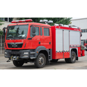
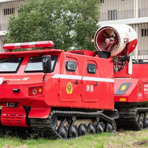
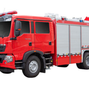
The tunnel fire truck is equipped with an engine and a transmission system, which can drive in two directions without turning around. The car is equipped with a positive pressure water mist exhaust system and a CAFS fire extinguishing system, which is efficient and fast. The cab oxygen supply system can be additionally configured according to customer needs.
2. The Whole Fire Truck’s Parameters
| No. | Main Items | Technical Parameters |
| 2.1 | Model | SXF5171GXFSD20 |
| 2.2 | Overall Dimension | 10300*2500*3700mm |
| 2.3 | Full Load Weight | 18000kgs |
| 2.4 | Number of the Crew | 6 (include driver) |
| 2.5 | Max. Speed | 90km/h |
| 2.6 | Capacity | 1600L Water & 400L A/B Foam. PP composite material liquid tank |
| 2.7 | Fire pump flow rate | 50L/s @ 10bar |
| 2.8 | Front fire monitor | 20L/s flow rate, 40m shoot range |
| 2.9 | Smoke Exhaust System | Positive pressure water mist type with 50000 m³/h displacement |
3. Special Chassis
| No. | Main Items | Technical Parameters |
| 3.1 | Manufacturer | CXFIRE |
| 3.2 | Model |
Optional |
| 3.3 | Drive type | 4*2 |
| 3.4 | Wheelbase | 5500mm |
| 3.5 | Engine model |
Optional |
| 3.6 | Engine type | Inline 6-cylinder, turbocharged, inter-cooled diesel engine |
| 3.7 | Rated power | 285Kw |
| 3.8 | Gearbox form | Automatic gearbox |
| 3.9 | PTO | Hydraulic clutch PTO |
| 3.10 | Fuel tank capacity | 260L |
4.1 Cabin
4.1.1 Structure: One Double Row Cabin and One Single Row Cabin.
4.1.2 Seats: 5 Seats in One Double Row Cabin and 1 Seat in Single Row Cabin.
4.1.3 Safety: Three-point pre-tightened seat belts are installed.
4.1.4 SCBA Setting: SCBA brackets are installed at the rear seats, and 6.8L-9L air cylinders can be placed.
4.1.5 Interior: PTO switch and alarm lights switches installed in the cab etc.
4.1.6 Lighting: Original lighting of chassis.
4.1.7 Step ladder: High-strength integrated non-slip step ladder.
4.1.8 Storage space: Storage box is arranged under the rear seats.
4.1.9 Air conditioning: fluorine-free environmental protection air conditioning system.
4.1.10 Handrail: Non-slip safety handrail.
4.2. Subframe
4.2.1 Material: High-strength special steel.
4.2.2 Performance: The liquid tank and the sub-frame are connected by elastic connecting seats with torque reduction performance, which not only increases the flexibility of the connection between the frame and the tank, prevents deformation and breakage of the upper body, but also increases the strength of the upper body.
4.3. Compartment
4.3.1 Material: All made of high-strength aluminum alloy profiles.
4.3.2 Structure: The frame of the carriage is all-aluminum alloy frame welded structure, and the outer skin is made of bonded aluminum alloy plates.
4.3.3 Roof guard: Made of aluminum alloy as a whole, with strobe warning lights and exterior lights installed outside, and LED roof lights inside.
4.3.4 Ladder frame: A set of multifunctional ladder frame is set on the top.
4.3.5 Rear ladder: An aluminum alloy safety ladder leading to the roof is set on the right side of the rear.
4.4. Roller Shutter
4.4.1 Material: Lightweight high-quality aluminum alloy.
4.4.2 Structure: A diversion groove on the top and a sealing strip around it, which has good rainproof and dustproof sealing performance.
4.4.3 Layout: The sides of the equipment box and the rear pump room.
4.5. Foot Pedal
4.5.1 Material: High-quality aluminum alloy profile.
4.5.2 Structure: Overall drawing structure of aluminum alloy profile, with a width of 50cm and a load-bearing capacity of more than 300kg.
4.5.3 Layout: Under the equipment box and pump room.
4.6. Electrical System
4.6.1 Warning light warning: Long row warning light are set on the top; The control devices are installed in the cab.
4.6.2 Equipment box lights: There are LED white lighting strips on both sides of the equipment box. The light switch and the rolling door are linked.
4.6.3 Strobe lights: Strobe lights for warning are arranged on the upper part.
4.6.4 Exterior lighting: LED lights for lighting are provided on the upper part of the compartment.
4.6.5 Roof lighting: LED lights are provided inside the top of the carriage.
4.6.6 Side Indicater Light: Built-in yellow indicater lights are installed on pedals.
5. Fire Fighting System
| No. | Main Items | Technical Parameters |
| 5.1 | Fire Pump with CAFS System | |
| 5.1.1 | Brand | CXFIRE |
| 5.1.2 | Model | CB10/50G |
| 5.1.3 | Rated Flow Rate | 50L/s @ 10bar |
| 5.1.4 | Vacuum Pump | Electric vacuum pump |
| 5.1.5 | Priming Manner | Automatic |
| 5.1.6 | Suction Height | 7m |
| 5.1.7 | Priming Time | ≤50s |
| 5.1.8 | Location | Rear-mounted |
| 5.2 | Front Fire Monitor | |
| 5.2.1 | Brand | Optional |
| 5.2.2 | Model |
Optional |
| 5.2.2 | Flow Rate | 20L/s @ 10bar |
| 5.2.3 | Shoot Range | 40m |
| 5.2.4 | Location | On the top of the tank |
| 5.2.5 | Control Manner | Remote Control |
| 5.2.6 | Horizontal Rotation Angle | -90°~+90° |
| 5.2.7 | Pitch Rotation Angle | -20°~+45° |
| 5.3 | Liquid Tank | |
| 5.3.1 | Capacity | Water 1600L, Type A Foam 200L, Type B Foam 200L |
| 5.3.2 | Material | PP composite material and Never Rust |
| 5.3.3 | Structure | 3 Tank Manhole; 1 Overflow Device/Pressure Relief Device; 3 Liquid Level Indicators; 2 Foam tank Drain Outlets with Valves; 1 Water tank Drain Outlets with Valves. |
| 5.4 | Control Panel | |
| 5.4.1 | Structure | Each fire extinguishing system is controlled by PLC, and different standardized control modules can be selected. IP56 protection level |
| 5.4.2 | Location | Rear pump room |


